

Why did I do this?

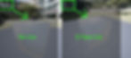
I have been working for a while to optimize my models. Texturing was one of the areas that I wanted to explore more. I already knew about cutting and packing UVs well and not to waste pixel space. Managing texture density-stretching and quality is something I also watched for and saved textures in multiple channels. However, a few technical aspects were beyond my knowledge before I started searching on how to improve video game performance. One of those discoveries was about UV seams, and hard edges count towards your total vertex count in a scene. These issues may seem trivial at first, but as soon as you start displaying several models in a scene, it will quickly chug away the hardware's performance. Perhaps this isn't an issue on a high-end graphics card, but it could be a problem on lower-end hardware and mobile devices. Here is a sample in Unreal 4 of the vertex count issue I found:
To reduce the final amount of vertex in a model, all you have to do is fewer cuts in the UVs and soften up the normals. Depending on the production goals, this could be a problem or not. Most 3D painting programs can ignore this issue. However, if the image is too distorted, it will be hard or impossible for a 2D artist to help with textures. Otherwise, the artist would have to learn Substance Painter, Mari, or 3D Coat to create extra "skins" textures for the model.
Asides from the hidden increased vertex count from UVs, I found out another thing related to texturing. Another culprit of slowing things down has too much material IDs; they will increase CPU draw calls. However, having fewer material IDs usually means less realistic visuals because you use fewer texture samples overall. You would have to lower and fit all the UV elements in one texture on a normal circumstance. Each geometric piece would be then competing for who takes more space of the textures resolution, or aka pixel density. Even if you used a procedural approach, you would still have to do masks, and those rely on pixel density. Stylized games don't tend to suffer much for lacking materials IDs because they use fewer texture samples, unlike the PBR method. That can depend on the project and the approach of the tech artists. So that's another reason why I ended up trying to do UDIMs in unreal.

Here is a link to a video that explains draw calls more in-depth:
For Those Who Don't Know UDIMs
If you know what UDIMS are you can skip to the next part. If you don't, well, UDIMs are quite useful for texturing complex objects. It is a method used mostly for cinematic projects to deliver high-quality visuals. In a nutshell, with UDIMs, you will end up with "patches", and they are treated as separate textures samples. Yet, all those patches are all projected in one material. So this method sounds like it would solve the Material ID draw call issues and the lack of texture sample output. The problem is, most commercial game engines don't generally support UDIMS until recently, through a plugin. For the most part, games use a technique called "Texture Atlases". It's meant to optimize by lowering CPU draw calls and memory usage, which is what I wanted. However, you will have the problem of pixel density that I mentioned before. In "Atlases", you put all the different textures in one texture sample, much like a collage of images. This comes at the cost of what object would have more pixel resolution. In production, one must find ways to compromise. Still, I don't want to lose that much quality over performance or spend money on a plugin. So with all this considered, I sailed on the idea of to simulate UDIMs in Unreal. I left some links below if you want to know more about each technique and the plugin.
How did I make it work?
So my Idea for UDIMs in Unreal came from how the texture atlas work. I realized a "Texture Atlas" was a precomposed UDIM system but in a 0 to 1 UV space. Instead of the machine doing it, the user creates it in an image editing software and then feed it to the engine. So I decided to replace the image editing software part for the Unreal Engine Material Editor. This technique would allow me to provide several texture samples from any size to make one "Texture Atlas". Then, the material can output it to the designated objects UVs.
First, I broke the process down on how I would do the atlas in photoshop. I needed to treat each image as a layer that I wanted to composite. For this, I used the linear interpolate (aka lerp) node to combine two images by using an alpha blend mask. Here is a quick image example for those who are unfamiliar with it.

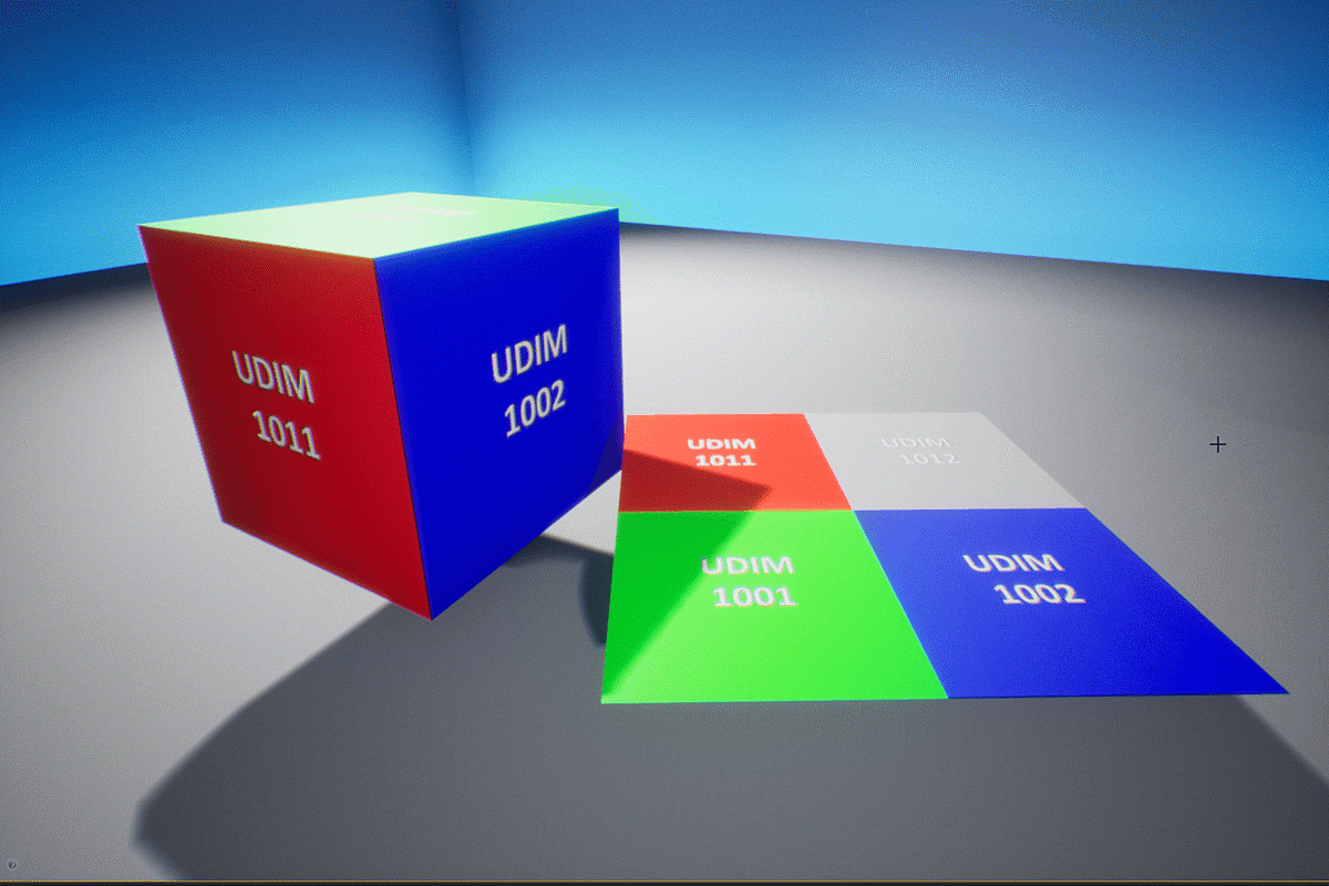
The tricky part was how I would place the images to fit all in a 0 to 1 texture coordinate space. Well, the answer was relatively simple; you have to tile the texture using a power of two number, so it places itself into a smaller form. Doing so could be considered equivalent of "moving and scaling" the texture in photoshop to put it in the texture atlas. Must note that the 3D model for the engine must have its UV "UDIM Patches" scaled down to fit the zero to one space so that they match the tiled textures. Ideally, the scaling down must be done after painting the object in a program that handles UDIMs like Substance or Mari. Here are a few images to illustrate how that process looks:
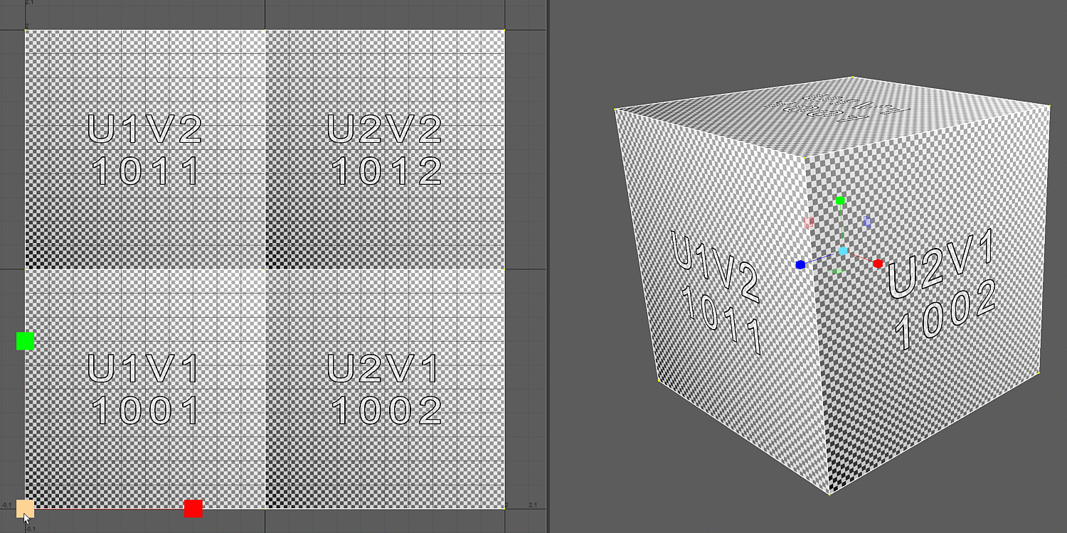

Now that I could place the images in the "UDIM patches", I decided to stay with a 2x2 square setup. This setup would allow me to collapse up to four material ID samples in one material. Moreover, this also determined how I was going to mask each layer against each other with the Lerps nodes.
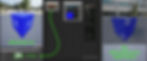
I tried two approaches for the masking process. One uses a low-resolution image of four pixels giving me a square tile type texture, and the other one was doing it procedurally. The reason why I ended up doing both is that shaders have limitations on texture samples. After I had already done my first test with the checker texture mask approach, I found out that a shader can't hold more than 16 textures samples. In mobile development, the limit lowered to 5 texture samples. So I didn't want to waste one of 5 or 16 texture samples for a mask. However, I did find a workaround that allows more texture samples to be used, but it doesn't work for mobile. Also, if you use that technique, it can increase the shader instructions, which can be bad. There is more information on overcoming the shader texture sample limit here. In a nutshell, the procedural way takes a bit more shader instructions. Still, it doesn't take a texture sample while the other form does the opposite. Here is how I made the masks work:


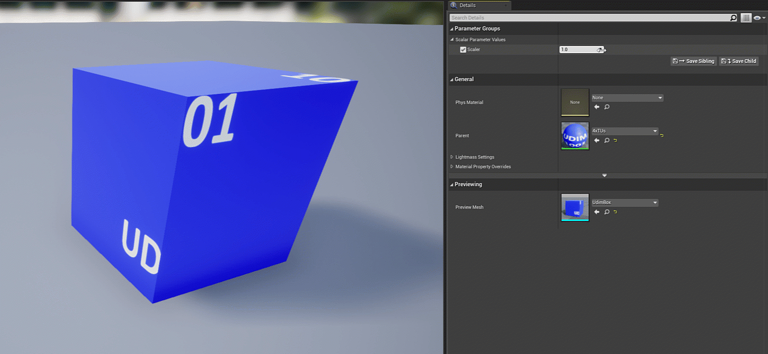
In the end, I got the result I wanted with these mask methods and the "scaled-down UV patch" technique. It lowered the material draw calls and kept texture quality. The shader instructions count seemed good too. One of the things I didn't test for was how lightmaps interact with it. Mostly, I did this thinking to optimize characters since they don't use lightmaps. Also for environments you can use "Virtual Textures"(click here to check it out). Still, I'm sure that with the proper setup, it can also work for environments. What is left to do is to test this in an actual project and profile the results. Here are some other images showing performance and quality tests:
While the difference isn't that big in this last example, there is one. Additionally, with more objects sharing a UV space, the pixel density/quality per mesh drops. So perhaps UDIMs techniques in UE4 can grant a performance and quality boost at the same time. Remember, I only showed here a 2x2 UDIM system, yet, I did manage to make a 4x4 UDIM work. All I did was raise the tile of the images and mask. Then, I funneled the 4x4 setup into a 2x2 system. That gave me access to 16 texture patches to outputs in a material. While that sounds cool, I considered the standard shader maximum limitations before showing examples of this post. I didn't want to show something that could only work on the PC. However, here is a brief example if you are curious.

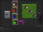
In order to use more textures than 16 textures, check this image below:
Green: Where to set the sample source to: "Shared-Wrap".
Magenta: Textures that only increased shader instructions and not samples quantity.

Wrapping Up!
Well, for now, this is all I got in terms of showing the technique itself. I will attempt to recreate the method on substance designer to combine with other game engines. However, before that, I will be testing this on some 3D characters and check out how it goes. This technique could shine in the mobile games despite the shaders having a 5 texture sample limit. It could also work well in virtual production, where high-resolution models with tons of detail are needed. Who knows? All I know I am not the only one wanting to use such system inside Unreal. It's not a perfect solution, but the benefits are excellent when used correctly. If you don't like my approach, you can try out forms that others have developed. I left some links below where they managed to get similar results that I did but with different methods. I hope this post becomes useful for someone and allows them to make their games run and look even better. Thanks for reading!
Approaches that I found from other sources: